Industrial X-ray Testing Company
RNDT provides Industrial X-ray Testing services. Industrial X-ray Testing, or Industrial Radiography, involves the use of ionizing radiation to view objects in a way that the could not otherwise be seen. Industrial X-ray Testing is a major element of Nondestructive Testing. Nondestructive testing (NDT) is a wide group of analysis techniques used in science and industry to evaluate the properties of a material, component or system without causing damage.
Industrial X-ray Testing is a method of inspecting materials for hidden flaws by using the ability of short X-rays and gamma rays to penetrate various materials. Two common ways to inspect materials for flaws or defects is to utilize X-ray computed tomography or Industrial computed tomography scanning.
The majority of radiography relate to the testing and grading of welds on pressurized piping, pressure vessels, high-capacity storage containers, pipelines, and some structural welds. When is comes to inspection, including weld inspection, there exist several exposure arrangements.
Panoramic is one of the four single-wall exposure/single-wall view (SWE/SWV) arrangements. This exposure is created when the source of radiation is placed at the center of a sphere, cone, or cylinder (including tanks, vessels, and piping). Depending upon the requirements of the client, the radiographer would then place film cassettes on the outside of the surface to be examined. When properly arranged and exposed, all portions of all exposed film will be of the same approximate density. It can also take less time than other arrangements since the source must only penetrate the total wall thickness (WT) once and must only travel the radius of the inspection item, not its full diameter. The biggest disadvantage of panoramic is that it may be impractical to reach the center of the item (enclosed pipe) or the source may be too weak to perform in this arrangement (large vessels or tanks).
Another arrangement is an interior placement of the source in an enclosed inspection item without having the source centered up. The source does not come in direct contact with the item. It is placed a distance away, depending on client requirements. An exterior placement has similar characteristics. The fourth arrangement is reserved for flat objects, such as plate metal, and is also radiographed without the source coming in direct contact with the item. In each of these arrangements, the radiographic film is located on the opposite side of the inspection item from the source. In all four arrangement, only one wall is exposed, and only one wall is viewed on the radiograph.
Of the other exposure arrangements, only the contact shot has the source located on the inspection item. This type of radiograph exposes both walls, but only resolves the image on the wall nearest the film. This exposure arrangement takes more time than a panoramic, as the source must first penetrate the WT twice and travel the entire outside diameter of the pipe or vessel to reach the film on the opposite side. This is a double wall exposure/single wall view DWE/SWV arrangement. Another is the superimposure, wherein the source is placed on one side of the item, not in direct contact with it, with the film on the opposite side. The superimposure is usually reserved for very small diameter piping or parts. The last DWE/SWV exposure arrangement is the elliptical. When using the elliptical arrangement, the source is offset from the plane of the inspection item (usually a weld in pipe) and the elliptical image of the weld furthest from the source is cast onto the film.
The beam of radiation must be directed to the middle of the section under examination and must be normal to the material surface at that point, except in special techniques where known defects are best revealed by a different alignment of the beam. The length of the weld under examination for each exposure shall be such that the thickness of the material at the diagnostic extremities, measured in the direction of the incident beam, does not exceed the actual thickness at that point by more than six percent (6%). The item or material to be inspected is placed between the source of radiation and the detecting device, usually the film in a light tight holder or cassette, and the radiation is allowed to penetrate the part for the required length of time to be adequately recorded. Lead is often placed behind the film to reduce ‘back scattered’ radiation, which can lead to the film becoming over exposed.
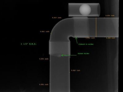
The result is a two-dimensional projection of the part onto the film, producing a latent image of varying densities according to the amount of radiation reaching each area. It is known as a radiograph, as distinct from a photograph produced by light. Because film is cumulative in its response (the exposure increasing as it absorbs more radiation), relatively weak radiation can be detected by prolonging the exposure until the film can record an image that will be visible after development. The radiograph is examined as a negative, without printing as a positive as in photography. This is because, in printing, some of the detail is always lost and no useful purpose is served.
Before commencing a radiographic examination, it is best practice to visually examine the component, to eliminate any possible external defects. If the surface of a weld is abnormally irregular, it may be desirable to grind it to obtain a smooth finish, but this is likely to be limited to those cases in which the surface irregularities (which will be visible on the radiograph) may make detecting internal defects difficult.
After this visual examination, the operator will have a clear idea of the possibilities of access to the two faces of the weld, which is important both for the setting up of the equipment and for the choice of the most appropriate technique.
RNDT Inc. provides nondestructive testing, industrial radiography, magnetic particle testing and more. RNDT, Inc. is an A2LA ISO-17025 accredited commercial testing laboratory headquartered in Johnstown, PA. Our field & laboratory services are offered to all industries. RNDT provides nondestructive testing in the form of industrial x-ray testing (industrial radiography), positive material identification (PMI), liquid penetrant, magnetic particle and ultrasonic testing and visual (CWI) inspections to most all industries. RDNT employs highly trained and experienced nondestructive testing professionals that hold current certifications conforming to the requirements of ASNT SNT-TC-1A & CP-189, National Aerospace Standard NAS-410 Rev. 3, Pressure Equipment Directive 97/23 EC for PED projects. These certifications satisfy global requirements for nondestructive testing personnel.


